
M1911 Milling Guide
Milling a 1911 frame is more challenging than milling AR lowers. In order to mill an M1911 frame successfully, you are going to need all the latest code, software, and hardware. Tolerance checks are built into the 1911 code which may require adjustment of the jig or manual alignment of the t-slot table.
Note | Your Ghost Gunner must be equipped with a V2 spindle and you must use the latest version of DDCut in order to successfully complete a 1911 frame.
Use the following information to address issues commonly encountered when milling a 1911 frame in the Ghost Gunner.
1. Order Of Operations
a. The M1911 cutting programs use the following operations to complete an 80% 1911 frame:
- Slide rail milling operation using a slotting end mill,
- Barrel seat milling operation using a stub ball end mill,
- Sear pin hole drilling operation using a #34 drill,
- Hammer pin drilling operation using a custom carbide 5/32" drill.
Note | The main 1911 cutting program ‘M1911_mill+barrelseat+drill.dd’ will run all four operations. It is located in Ghost Gunner/Cutting Code/M1911 Code/
2. Additional Code and 9mm Frames [Clark/Para]
a. If you’d like to run a specific operation, chapters of the M1911 cutting program can be found in the Additional M1911 Code folder.
- M1911 rails.dd completes the slide rails using a ¼” slot cutting end mill.
- M1911 barrelseat.dd completes the barrel seat using the ¼” ball end mill.
- M1911 drill completes the sear and hammer pin holes using a #34 drill and custom carbide 5/32” drill.
b. The M1911 9mm frames use a modified version of the code without barrel seat cutting operation.
Ghost Gunner 3 | 1911_9mm_10mm_40_38super.dd
Ghost Gunner 1 & 2 | 1911_Rails+Drill(9.10.40.38super).DD
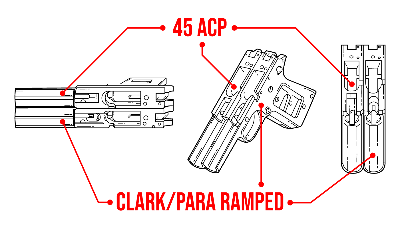
3. Verify you are using a compatible frame
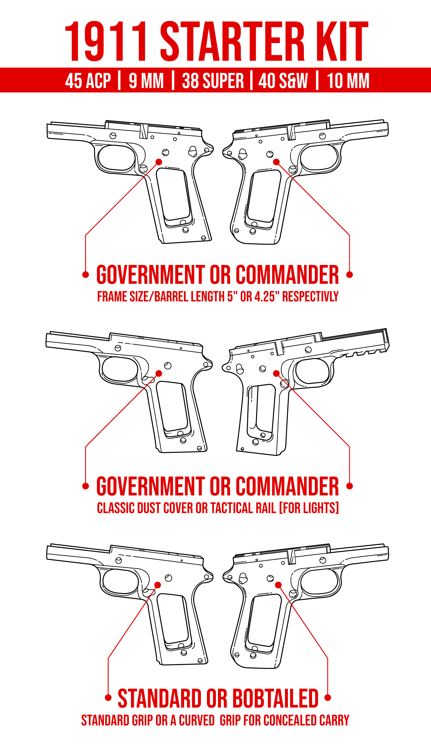
a. We currently offer Series 70 Government (.45 ACP, 5" barrel) raw billet 7075 aluminum frames, Series 70 Government (9mm/10mm/.38SUP/.40S&W, 5" barrel) raw billet 7075 aluminum frames, as well as M1911 cutting code and jigs designed for specifically for those platforms. M1911 frame by Stealth Arms.
Caution | Do not use steel frames. The Ghost Gunner 1 & 2 is limited to milling 7075-T6 Aluminum or softer materials. The Ghost Gunner 3 can mill steel, but we have yet to release software.
4. Verify you are using the latest version of DDCut.
a. DDCut V2.02.006 for Windows or V1.0.9 for mac is required to run calculations required to mill pistol frames. DDCut Windows V2.02.009 and DDCut Mac V1.0.9 are included on the USB drive with 1911 code. Uninstall older versions of DDCut and install the latest version. Using an older version of DDCut will result in repeated probe failures and possible damage to the frame.
5. Electrically isolate the jig to avoid probe errors.
a. Over-tightening bolts can cause the jig to short to the t-slot platform. Make sure to snug the bolts according the directions. Otherwise, you may receive an error about the part shorting to the table. Check for 5 Volts DC between the frame and t-slot platform while snugging bolts. If the voltage suddenly drops to zero, loosen bolts slightly until you read 5 V DC (+/-0.5V).
M1911 Aluminum Jig | If you continually get a short when mounting the jig to the t-slot platform, carefully apply an even layer of packing tape to the bottom of the 1911 jig to help insulate it from the t-slot platform.
6. Verify Endmill Placement
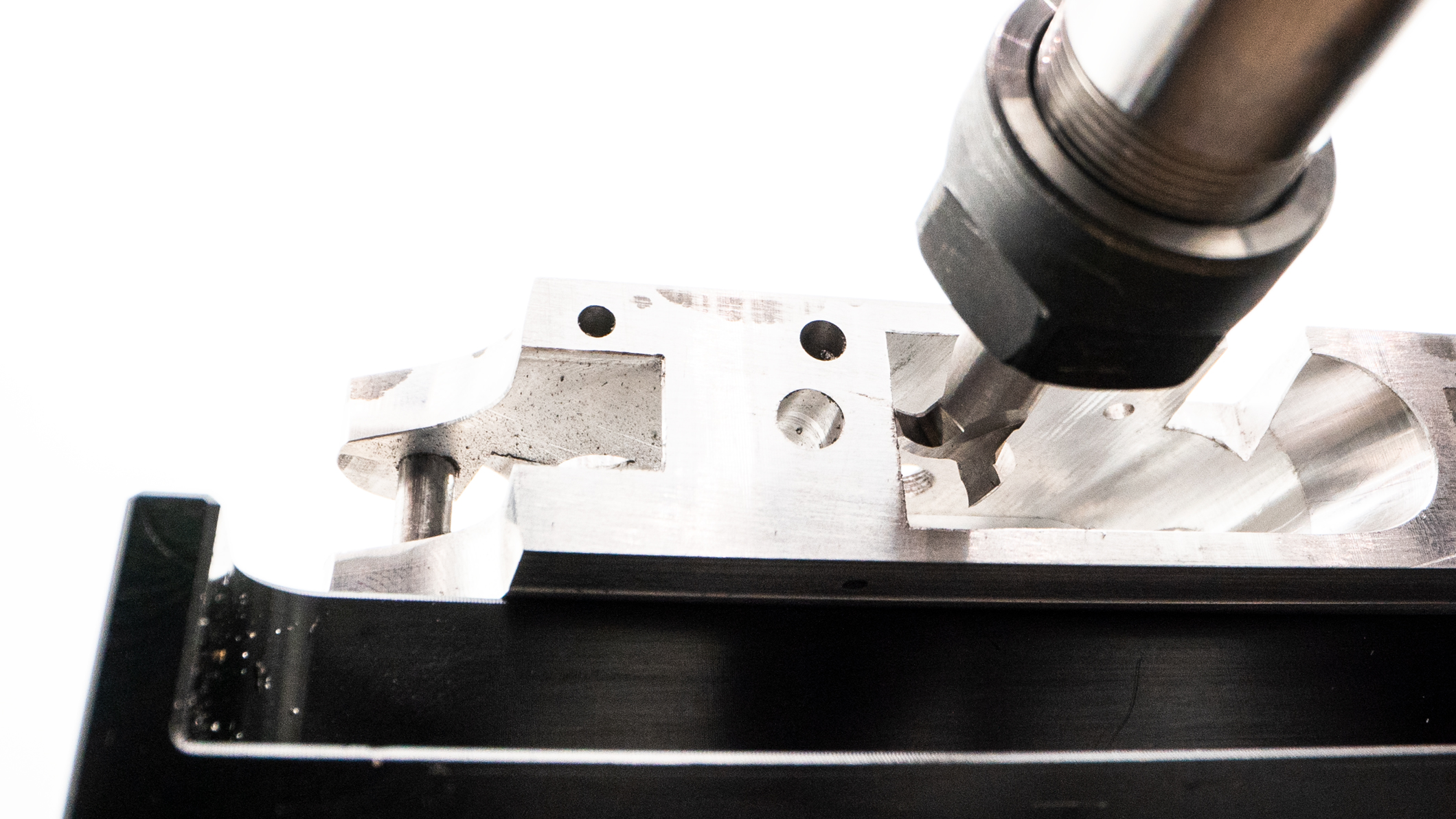
Verify the slotting end mill is centered in the magazine well when first placing the frame-jig assembly in the work bay. Use the following images to verify the slotter is centered in the 1911 mag well. Prior to the probe sequence for the rail slot cutting operation:
a. Rotate slotter flute right then slide frame left and snug jig bolts as depicted below.
b. Then rotate slotter flute left after snugging bolts to move away from frame.
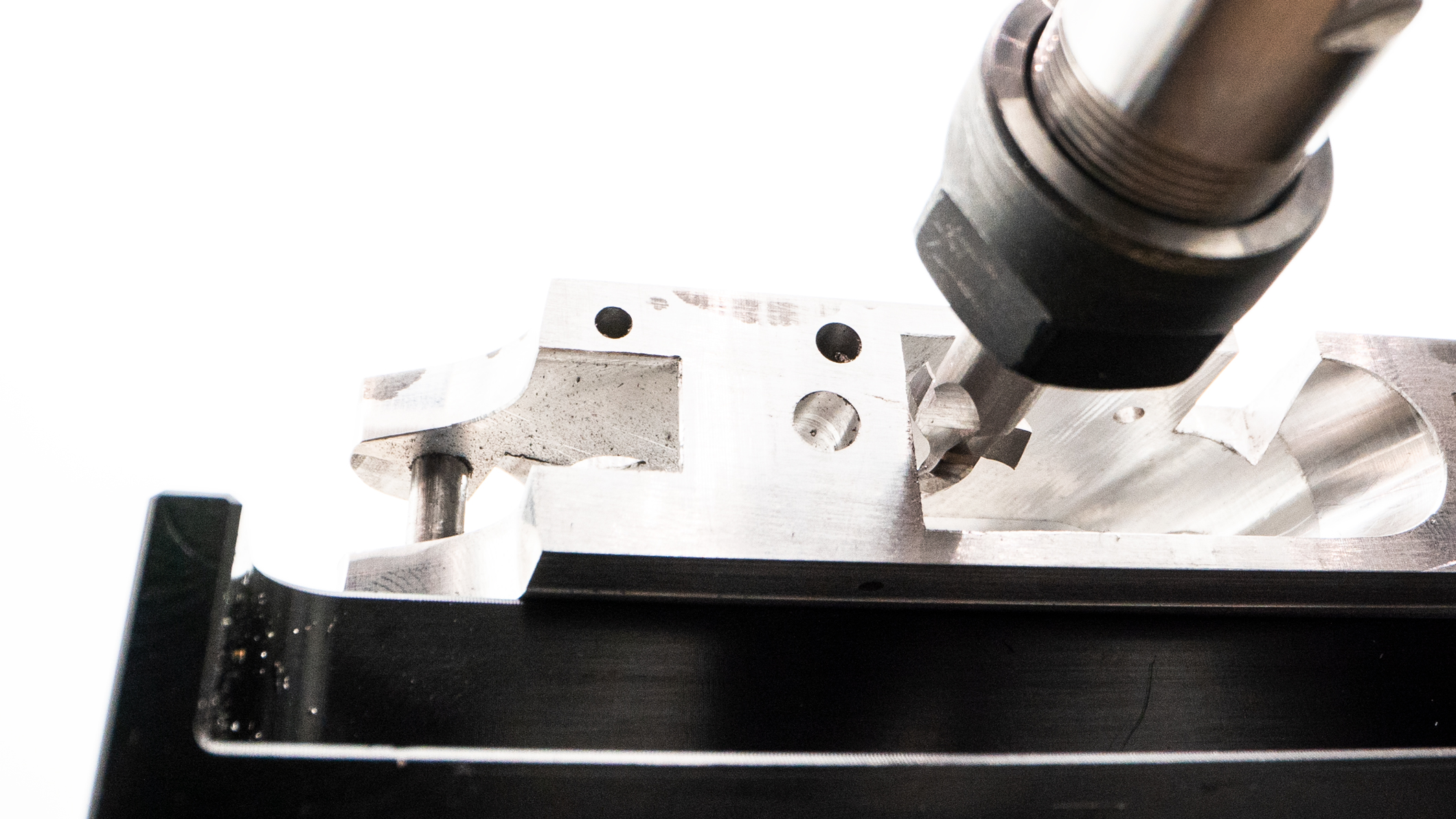
c. If the slot cutting end mill is too high in the 1911 magazine well and makes contact with the inner left side of the frame upon starting to spin up, shut down the program and run Reset from the Troubleshooting Code folder. After that, proceed to run the 1911 milling program.
Initially place the jig so it is parallel to the t-slot rails in order to reduce the need to repeatedly probe the frame and adjust the jig.
For the tolerance check steps, make sure you keep the left two bolts loose enough that the jig can slide when the end mill moves to nudge the front of the frame. When prompted to snug bolts for the rail cut, verify that bolts are threading properly into their respective t-slot nuts, and that they are just snug enough to secure the jig squarely to the t-slot platform.
Z-axis out of tolerance: There is a significant difference between the z position on the top-front of the frame and the top-rear of the frame. When snugging the "anchor" bolt, pull jig towards you, to remove any slack there could be on the rails. Then align the jig so it's close to parallel to the table. Push the left side of the jig forward so that the frame makes contact with the tooling when prompted in order to true the frame's z axis position. It may take numerous attempts.
X-axis out of tolerance: There is a significant difference between the x position on the side of the front of the frame and the same side of the rear of the frame. The workpiece may be improperly mounted to the jig ,or the jig may be improperly mounted to the t-slot table. Otherwise, the t-slot platform is likely slightly higher on one side than the other.
a. Follow the procedure in this video to true your t-slot platform on GG1 & GG2. You can use the ¼” end mill used for the AR milling program.
https://drive.google.com/file/d/1gx0B33X4A3adbdz3M_ZTRwNYou-PihjG/view?usp=sharing
b.If you have a GG3, there is an X auto level function if you go to Settings > Machine Actions > Auto-Level X Axis
c. If you keep getting the X out of tolerance, check that the jig sits flat on the table as well as the frame.
Comments
0 comments
Please sign in to leave a comment.