
The Probe Circuit
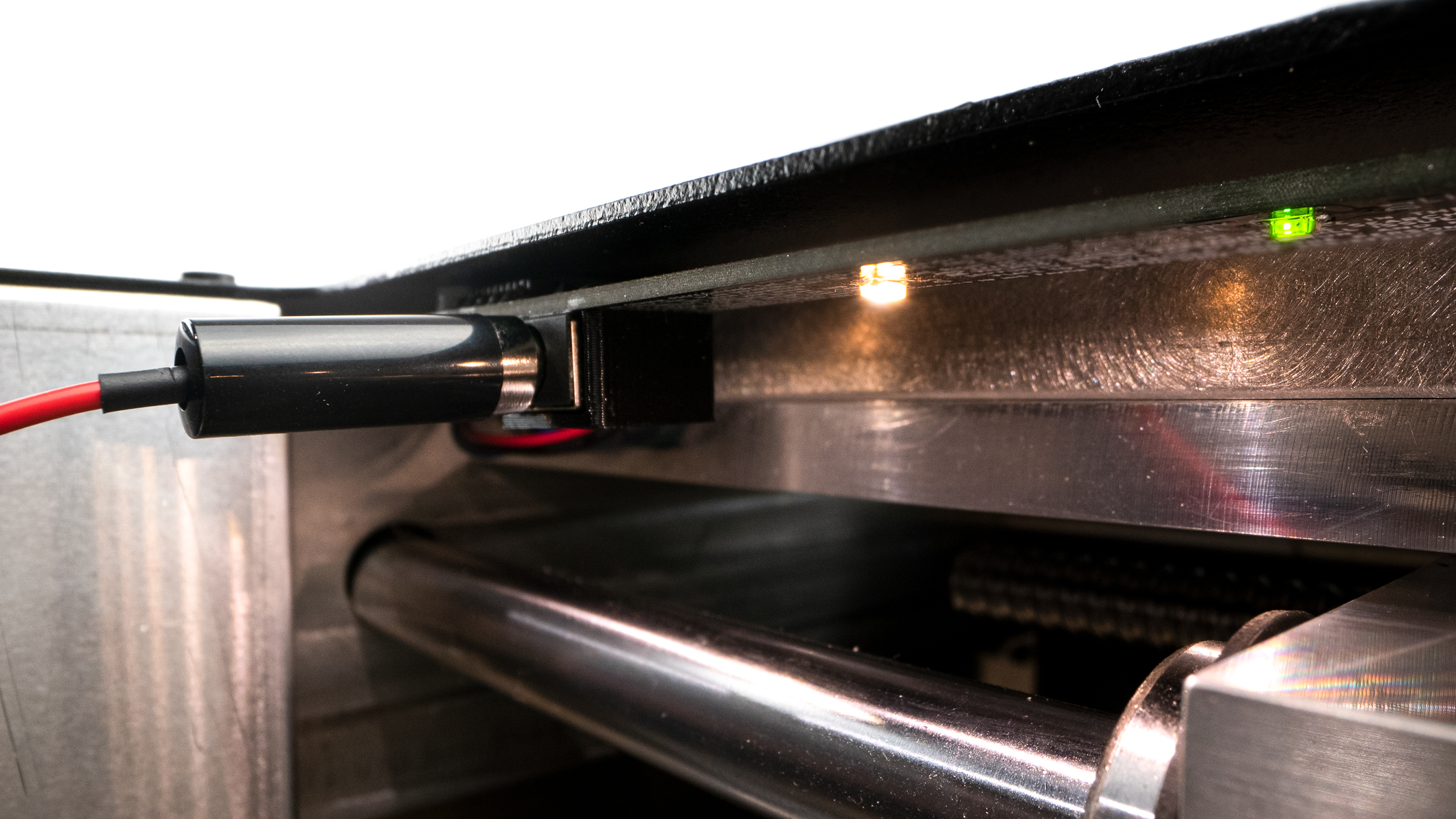
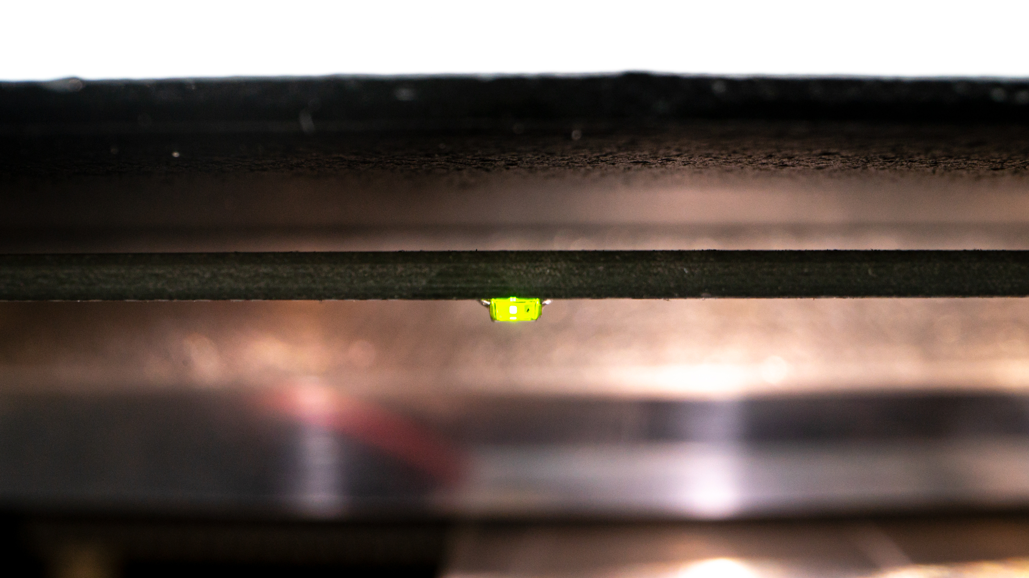
Ghost Gunner utilizes electric probing to orient itself for cutting, for a successful cut verify connectivity before every operation. Ghost Gunner 3 features a green LED, pictured above, to indicate when the 5v current is tripped. Ghost Gunner 1 & 2 users can check the voltage with a standard multimeter.
Note | The USB cable connection to your computer powers the Ghost Gunner’s probe circuit with a 5 Volt DC electrical signal.
General Troubleshooting
If the workpiece is not properly connected to the probe wire or shorted to the t-slot platform, the end mill may bore into the workpiece during the initial probe. Usually this occurs on the first probe on top of the bolt catch. Avoid this situation by ensuring that 5 volts DC is detectable when touching voltmeter leads between the lower and the spindle.
1. Dial your voltmeter to 20 Volts DC and touch one voltmeter probe to exposed metal on the lower. Proceed to touch the other probe to the spindle to verify the 5-volt signal required to locate the workpiece. The probe signal is detectable by the computer if it is between 4.5- and 5.5-Volts DC.
2. If you are unable to detect 5 Volts DC between the workpiece and the spindle using a voltmeter, verify that the red probe wire is getting voltage. With the GG’s USB cable connected, hold the probe wire away from the machine and use a voltmeter to measure the voltage between the eyelet of the red wire and the t-slot table. It should read around 5 Volts DC between the probe wire and spindle. The probe signal is detectable between 4.5-5.5 Volts DC.
3. If you are unable to detect 5 Volts DC between the probe wire and the spindle using a voltmeter, there may be an issue with your computer’s USB port. Try using a different USB port. Try a different USB cable. The problem may be with your computer. Make sure the computer is plugged into a grounded outlet and that the computer’s power settings are set to always on.
4. If the probe circuit is functional, the problem may be with your jig setup or tooling. Something is interfering with the probe circuit.
GG3 Specific Troubleshooting
The Ghost Gunner 3 is equipped with a green LED light that will turn on whenever the part is shorted to the table, the endmill is making contact with a charged workpiece or if the probe wire is unplugged.
1. Use this feature to help you detect any possible probing issues before you start the probing sequence. When the workpiece is installed and ready for probing, make sure the end mill is not contacting the workpiece. The green LED light should be off at this point. If it’s on, the workpiece may be shorted to the table.
2. To check if your workpiece is getting voltage, you can short the part to the table by using a metal Allen wrench. Touch raw metal on the workpiece with one end of a wrench, then touch the endmill or table with another part of the wrench, so that the wrench is touching both the workpiece and the table or spindle at the same time. The green LED light should turn on when the part is shorted. Remove the wrench and make sure the green LED turns off. Then proceed to probing.
Cleaning
An aluminum chip can cause an electrical short to occur between the workpiece and the t-slot plate. Because of this, make sure to vacuum the work space between steps. Check that the jig mounting bolts and washers don’t make contact with the lower. Make sure the trigger guard is not contacting the t-slot plate. Apply tape under the trigger guard if it appears to make contact with the t-slot plate.
Note | AR-15 and AR-308 trigger well cut probe sites are on top of the bolt catch site, in the center of the rear mag well wall, and in the left mag well wall. Holes cut probe sites are in the corner on the right side of the grip tang.
Comments
0 comments
Please sign in to leave a comment.