
Diagnosing Selector and Pin Hole Offsets
There are various things that could be going wrong leading to the offset issues that you are experiencing. Therefore, in this article, I will tackle a few different scenarios, one of which you are most likely experiencing. If this article doesn’t help, don’t hesitate to call our support number.
1. Verify Codes
There is a possibility that the cutting codes you are using are out of date. If you are working on an AR-15 or AR-308 lower, make sure that the codes are dated no older than August 20, 2018.
Ghost Gunner 1 & 2 | "Ghost Gunner 1 & 2 2020.04.28"
Ghost Gunner 3 | "Ghost Gunner 3 2020.04.22"
If you use the “pins.dd” or “selector+pins.dd” cutting code files, be sure to start the machine with the 1/4” end mill installed, not the 5/32” drill bit. The 1/4” end mill is required to accurately probe. Probing with the drill bit will cause the holes to be milled 0.094” upward from the correct position.
2. Check Proper Tool Installation
The problem you’re facing could be due to an unsecured tool. Make sure the collet is properly seated into the collet nut. The collet should snap into the collet nut when turned at a 45-degree angle. This will ensure that the collet and nut do not come apart. Slide the tool into the collet-nut assembly. Thread the tool-collet-nut assembly onto the spindle. Push the tool all the way into the spindle then tighten the collet nut to ensure that the tool does not walk out while milling. The collet should not be able to fall out of the collet nut once snapped together.
Here's a video of an ER collet system on a different CNC machine. The video is not of the Ghost Gunner, but the method shown is exactly the same.
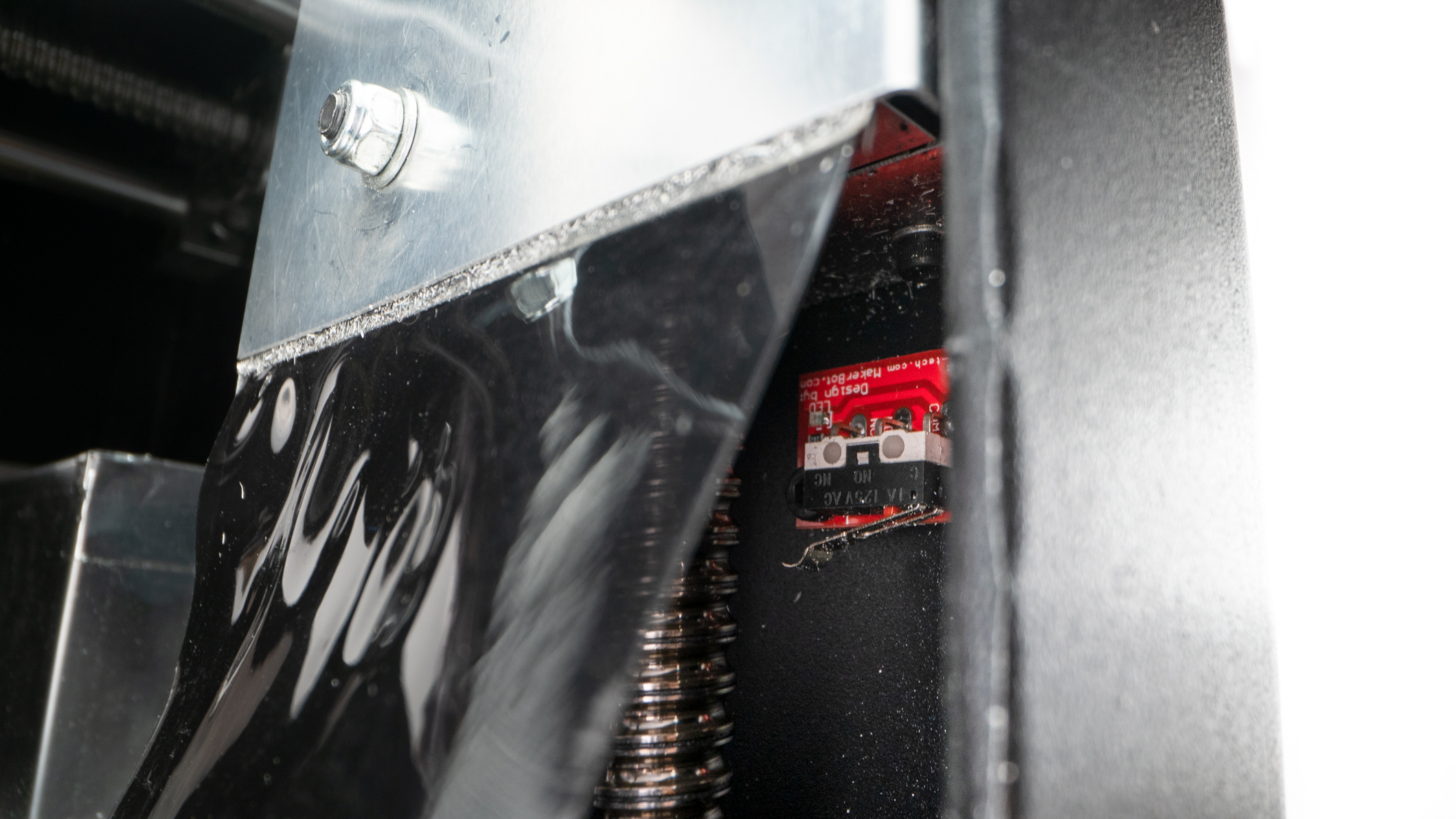
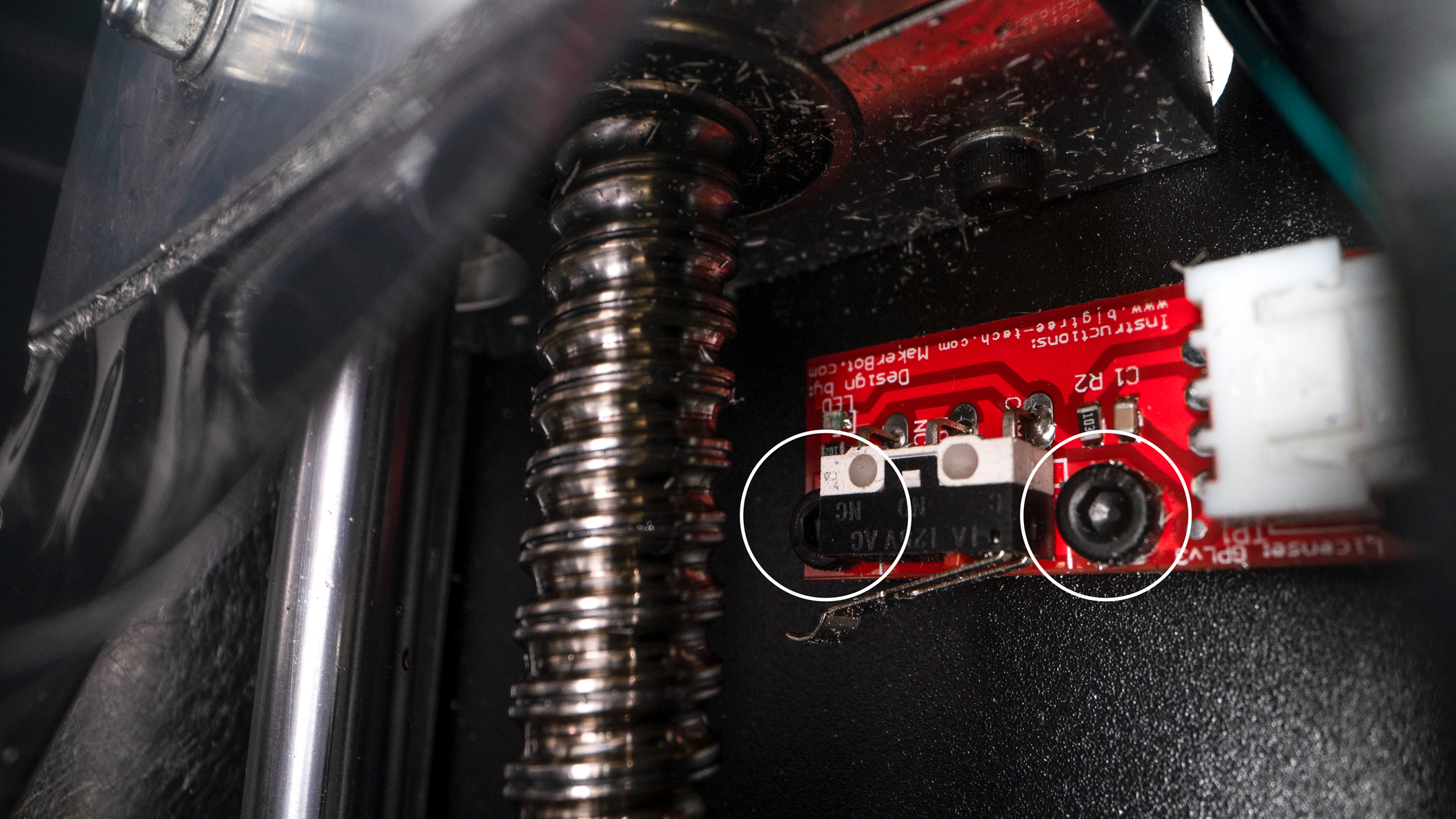
3. Adjusting X-Limit Switch Position
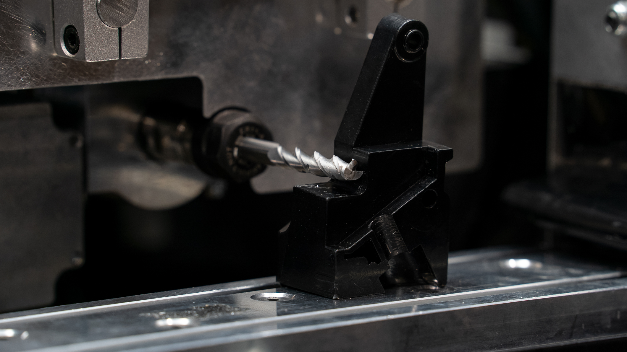
If the end mill is too high over the right jig during the selector probe sequence, it may probe the curved portion of the upper-front grip tang. This causes the selector and pin holes to be cut slightly rearward from spec. Prior to the Selector Probe operation, the end mill should be nestled in the corner formed by the right jig. The end mill should contact the right jig piece or be no more than 0.010” above it. You may need to adjust the X-limit switch position so the t-slot platform homes at the correct height.
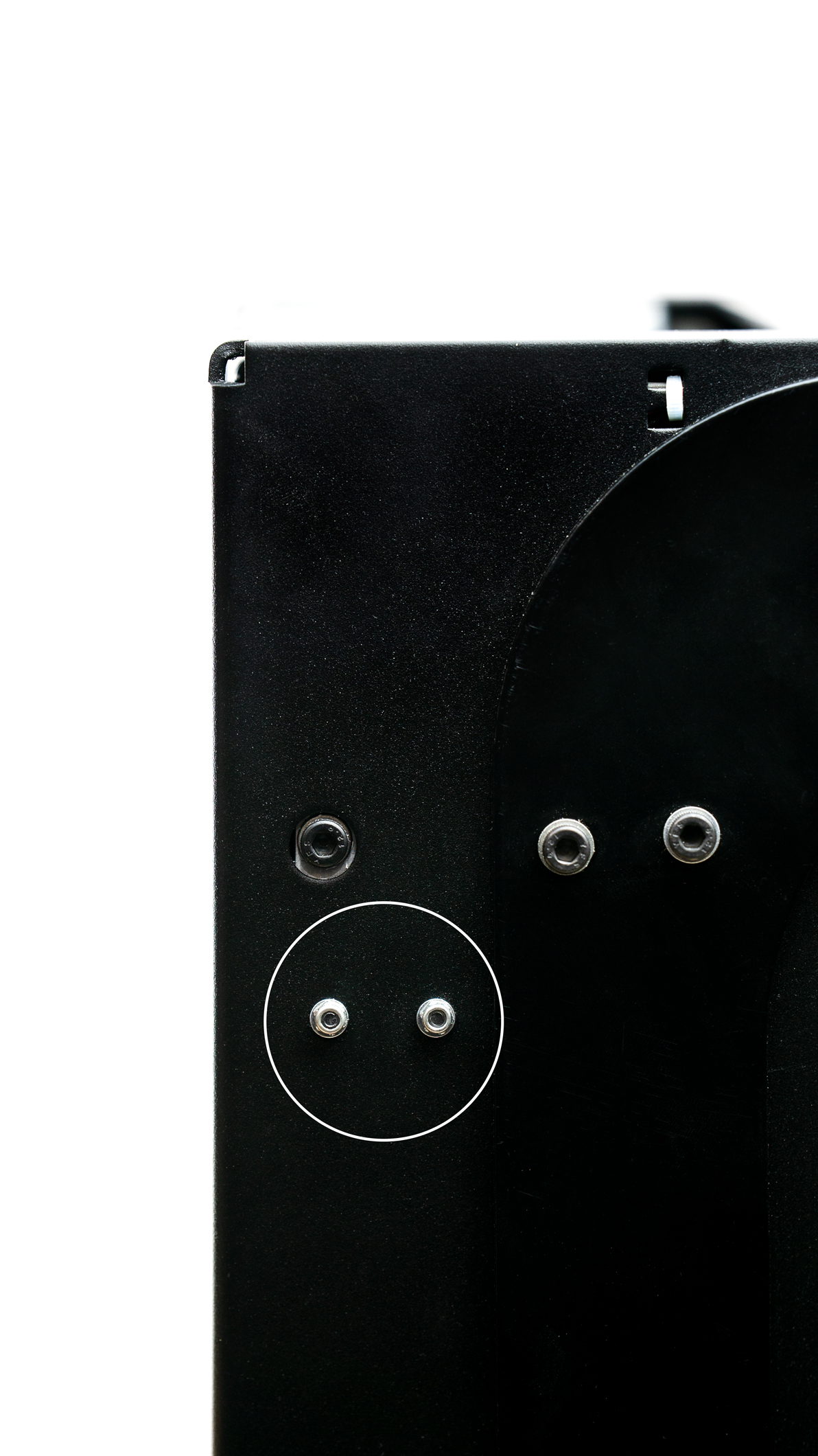
a. Use the following images to locate and adjust the x limit switch.
b. The end mill should contact the right jig piece or be no more than 0.010” above it, shown at the top of the article.
c. You may need to adjust the limit switch downward if it is digging into the right jig piece. Adjust it up if the end mill hovers over the right jig piece.
c. You may need to adjust the limit switch downward if it is digging into the right jig piece. Adjust it up if the end mill hovers over the right jig piece.
Comments
0 comments
Please sign in to leave a comment.