
Adjusting AR-15/308 Fire Control Group (FCG) Pocket Placement
The following instructions detail how to access and edit cutting code to adjust the position of the FCG pocket’s left-right position (X Axis), as well as its forward-rearward position (Y Axis). AR-15 codes are used as the example in this article, but the instructions will work for any AR variant.
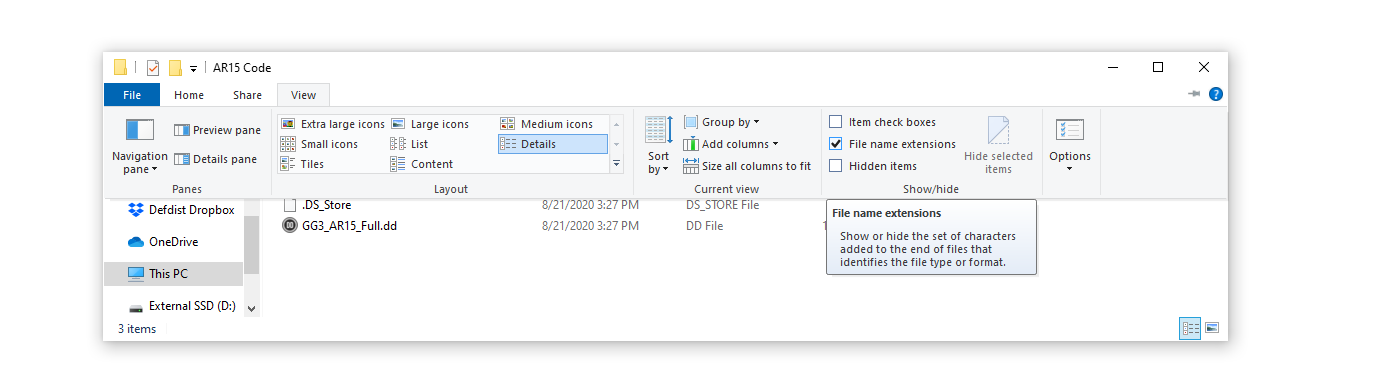
Caution | ‘Hide extensions for known file types’ must be disabled in Windows File Explorer Options view tab.
1. First, you will want to make a copy of the existing .dd file, and paste it to a folder on your desktop.
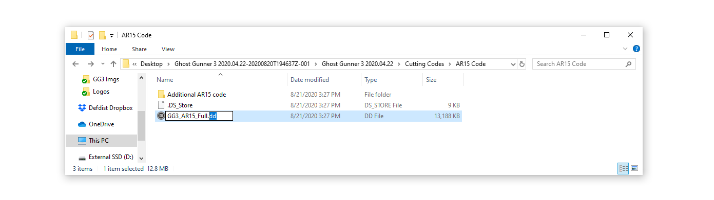
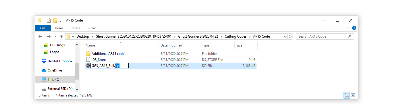
2. Change the extension of a .dd file to a zip file. For example, change AR15-pocket+selector+pins.dd to AR15-pocket+selector+pins.zip.
3. Use WinZip to extract the contents any .dd file. This includes the manifest file that contains codes for directing which files are executed during the program. This also includes an Image folder containing .jpg images displayed in each step of a program. You can also extract the Code folder, which contains .txt and .nc files. These contain g-code executed by the manifest file for each step of a program.
Note | Text files containing g-code can be edited using a basic text editor.
Note | Notepad++ is a free program that can be used to edit .nc and .yml files.
Note | The manifest.yml file is the master file that executes g-code text files and instructional text, as well as displays images contained in the code and image folders.
4. Open the Well Probe text file in the Code folder.
Y-Axis: To adjust the pocket position forward, adjust the Y value for the pocket position by editing the following line of code:
G10 L20 P2 Y0.125
Add to the Y value to move the pocket backward, subtract to move the pocket forward.
The front FCG wall should be 0.100” thick.
For example, say you measure a front FCG pocket wall thickness of 0.080” on a particular brand of lower.
0.100 - 0.080 = 20
The appropriate adjustment of 0.020” backward is added to the existing offset of 0.125” to equal a total 0.145” offset for the Y axis. The adjusted code is shown below.
G10 L20 P2 Y0.145
This example will result in a 0.100” front pocket wall on the next lower of the same brand/dimensions.
X-Axis: To adjust the pocket position left/right, adjust the X value for the pocket position by editing the following line of code.
G10 L20 P2 X+.324
Edit the x offset to a value appropriate to your measurements. Subtract to move the pocket right, add to move the pocket left.
This is the formula for centering FCG pocket based on a previous (off-center) cut of the same brand lower using standard AR15-pocket+selector+pins.dd code:
L = Left wall thickness
R = Right wall thickness
(L-R)/2 = W
W = value to add to existing X offset to center pocket
For example, say you have a left wall that's thinner than the right wall. In this case, you should get a negative value. If your walls were L = 0.100" and R = 0.120", you should get a W value of -0.010".
So the existing x offset of .324 plus -0.010 results in an x offset value of .314".
This will shift the pocket center 0.010" to the right.
The final code should look like this for this example:
G10 L20 P2 X+.314
5. Save changes to the Well Probe text file.
When you've completed your custom code, compress all the files in a .zip archive and change the file extension to .dd so it can be recognized by DDCut. Select the manifest, code, and image files so they are all highlighted and right click to ‘add to archive’. Select the .zip option in the WinZip window. Once the zip file is created, rename it’s extension to a .dd file.
6. Run your edited .dd program through DDCut.
Comments
0 comments
Please sign in to leave a comment.