
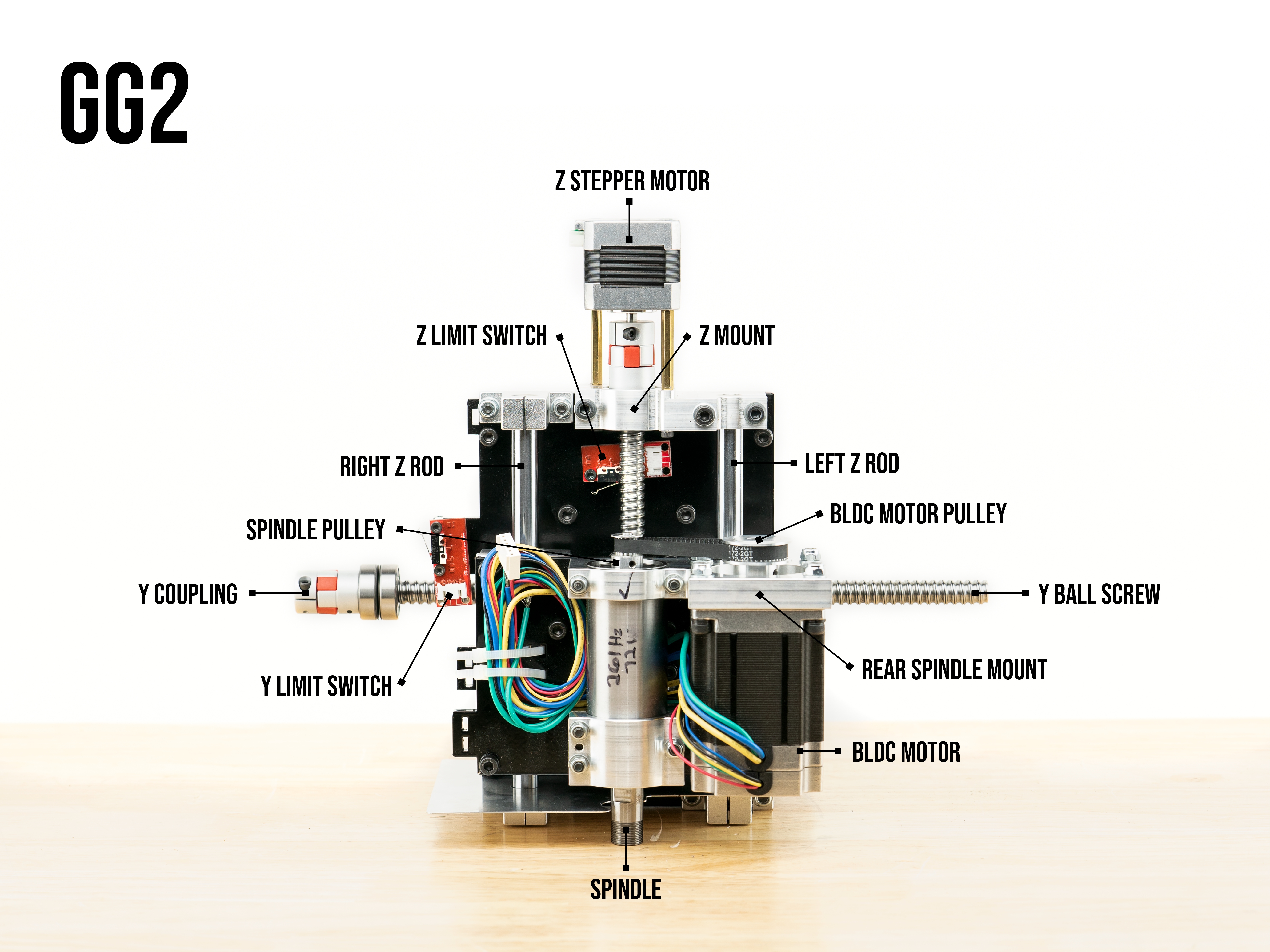
GG2 Z-Axis Repair
Follow these instructions if the ball screw is detached from the Z mount.
Tools required |
- 2.5mm allen
- 4mm allen
- 8mm open ended wrench
- Torque wrench
1. Turn Ghost Gunner over so the bottom is facing up
2. Remove the back plate by unscrewing seven bolts with 2.5mm allen.
3. Center the Y/Z gantry by rotating the Y coupling on the side of the machine.
4. Loosen the set screw on the Z coupling closest to the Z stepper. (2.5mm allen)
5. Unplug the z stepper motor’s wires and cut the zip tie holding the wires to the brass stand off.
6. Remove the 3 M5 bolts on the z stepper mount with a 4mm allen and an 8mm open ended wrench.
7. Slide the z mount and stepper off the rod and ball screw removing it from the assembly.
8. Loosen the set screw on the z coupling nearest the bearings and remove coupling from the ball screw.
9. On the ball screw, there are two bearings with two belleville springs in between them. Rotate the bearings by hand to make sure they spin smoothly and aren’t gritty.
10. Verify that the belleville springs are orientated correctly between the two bearings. There are three ways to orientate the bellville springs. For the correct orientation, make sure the outer edges of the two springs are not touching one another.
11. Now that you have verified the bearings are smooth and the belleville springs are correctly orientated, put the coupling back on the ball screw. Before you tighten the coupling, press it as tightly against the bearings as possible to compress the belleville springs in between the bearings. Now tighten the coupling to the ball screw (2.5mm allen) while firmly holding the coupling tight against the bearings. Be sure the coupling is tightened down as hard as you can get it.
12. Make sure the belleville springs are flush with the bearings.
13. Slide the z mount and stepper back onto the bearing, and rod onto the plate.
14. Insert the 3 M5 bolts and nuts back into the z mount.
15. Tighten the left and center M5 bolts on the z mount (not the one on the right nearest the ball screw bearings).
Note | While you tighten the left and center M5 bolts, pull the z mount towards you so there is a slight overhang of the z mount to the y plate. Make sure the z mount and y plate are parallel.
16. Make sure the bearings on the z ball screw are flush inside the z mount. Tighten the right M5 nut and bolt on the z mount with a torque wrench set to 30 lbs.
17. Tighten the bolt on the z coupling nearest the stepper with 2.5mm allen. Make sure it is very tight.
18. Rotate the z coupling so the gantry moves toward you and confirm that the z gantry still trips the limit switch. You should hear a soft click.
19. Plug z stepper back in and zip tie extra slack in the wires to the brass stand-off.
20. Reattach the back plate. (7 bolts, 2.5mm allen)
21. Check that components were installed correctly. The machine should be able to home successfully.
Comments
0 comments
Please sign in to leave a comment.