
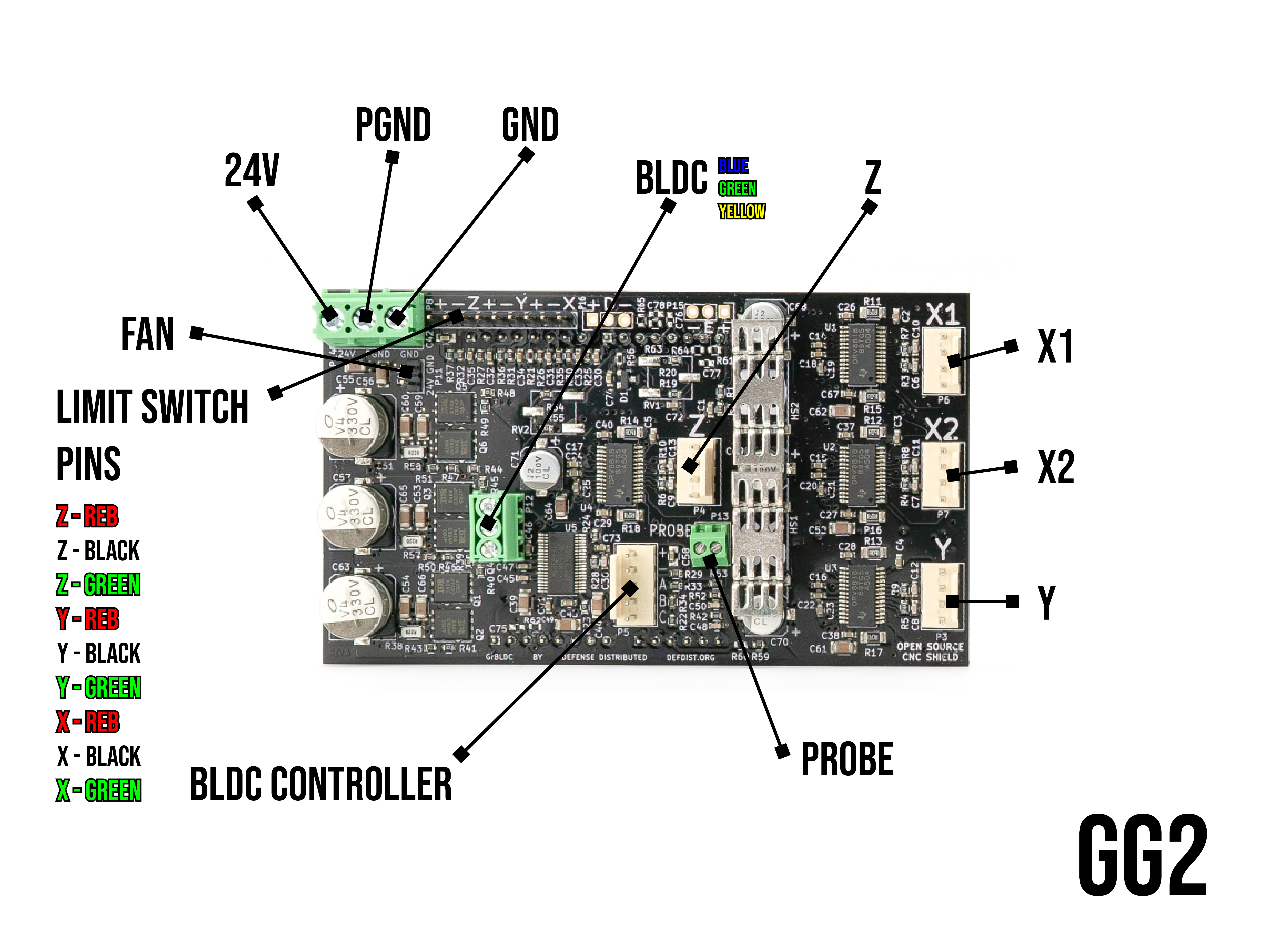
Ghost Gunner 2 Control Board Wiring
1. Use a 2.5mm allen to remove 7 bolts securing the Ghost Gunner’s rear panel.
2. Turn the machine upside-down. Take care not to lean it on its stepper motors.
Caution | Do not disconnect wiring from control board. If you must disconnect wiring, label wires to the control board before disconnecting them.
Caution | Aluminum chip can cause electronics to short. Thoroughly vacuum all aluminum chip. Use a paintbrush to free up any chip stuck to components. The inside of the machine must be completely free of aluminum chip prior to opening the electronics enclosure.
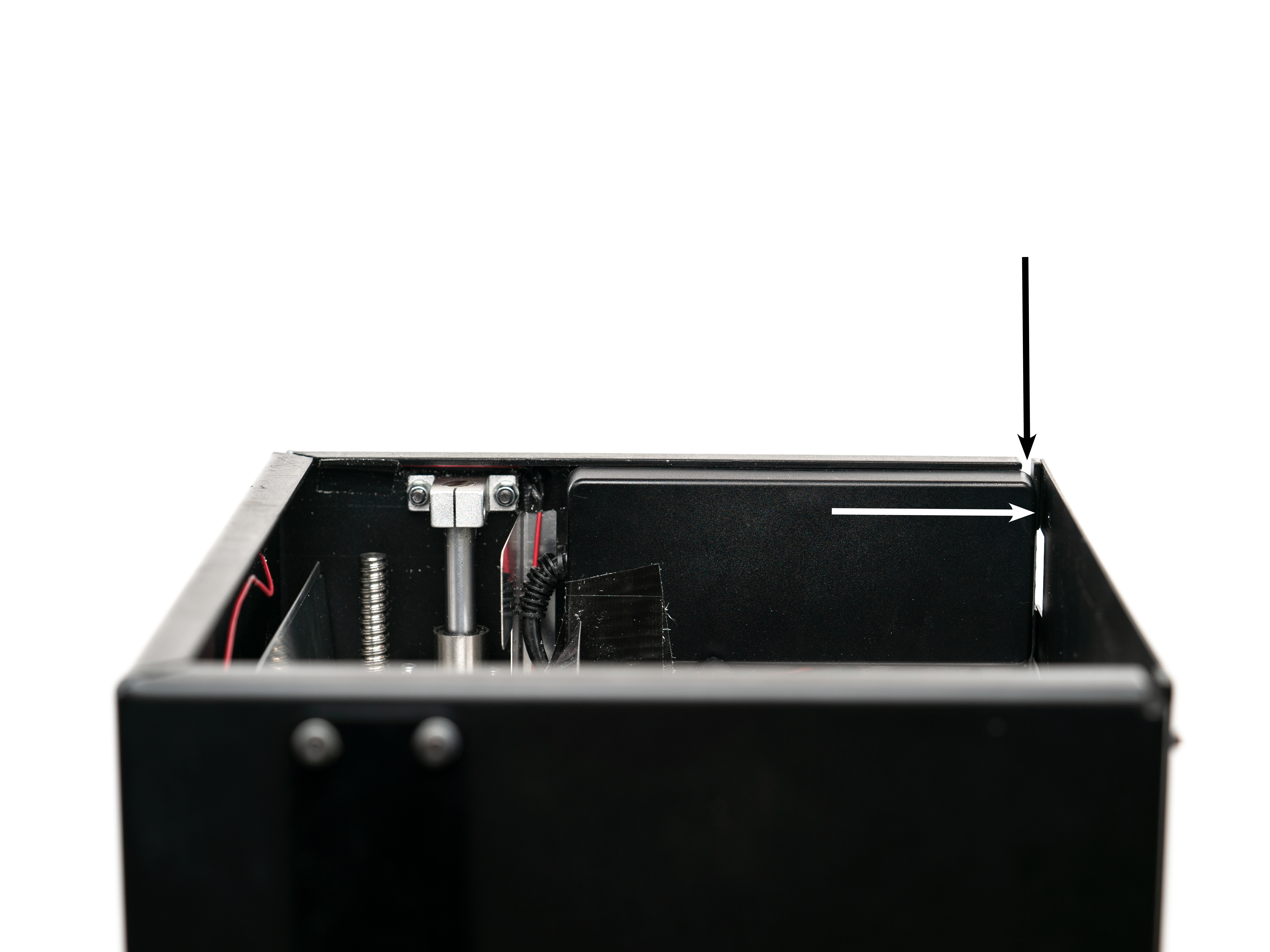
3. The power supply is held tight to the inner wall of the machine with an adhesive. Pry the power supply off of the wall using a large flathead screwdriver inserted from the slot in the corner as shown in following image (A1). It requires a great deal of force to break the power supply away from the VHB tape so don’t hesitate to put to some muscle into it.
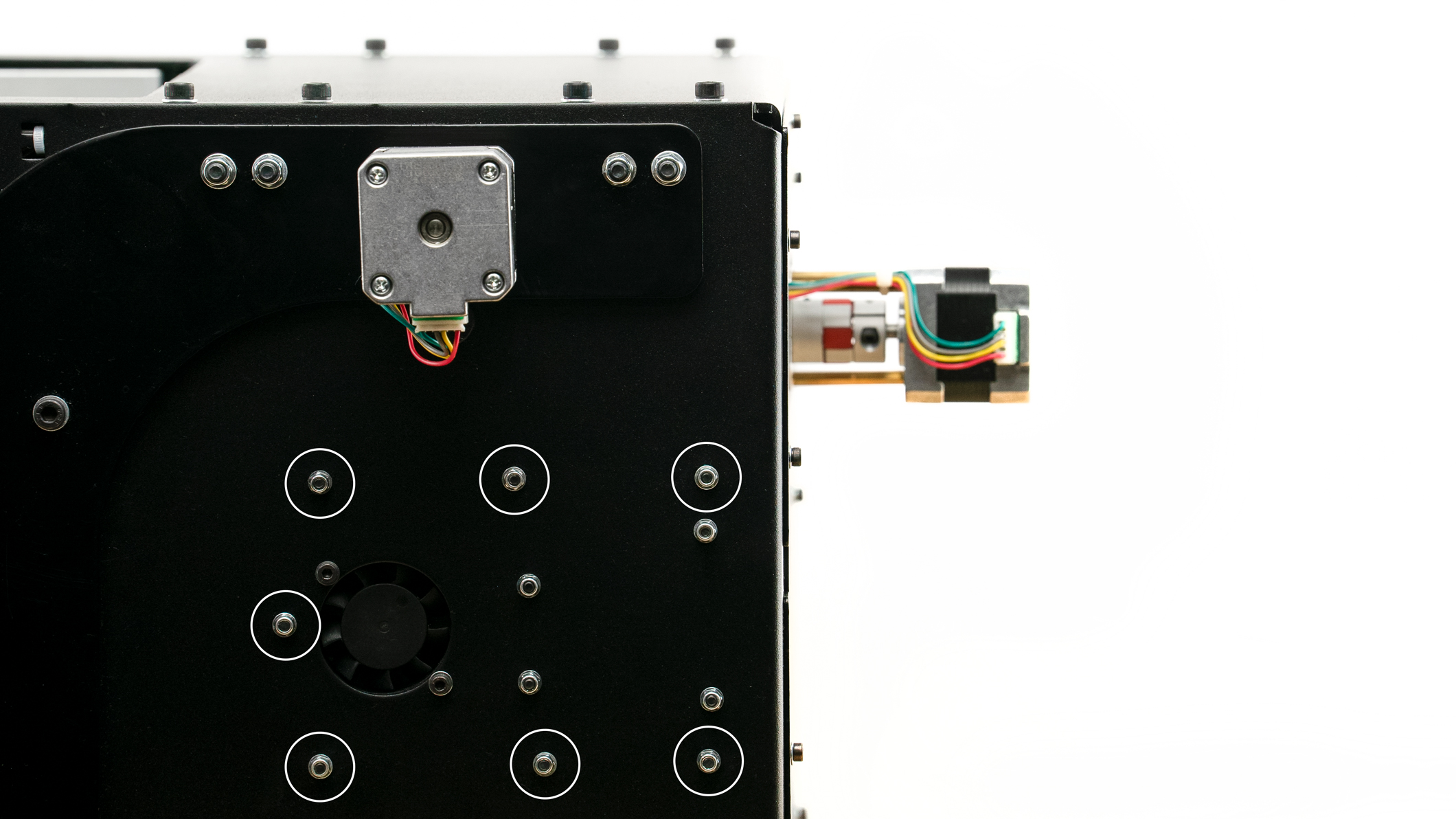
4. Use a 2.5mm allen and 5.5 mm socket to remove 7 bolts that secure the electronics enclosure to the wall as shown in below image (A2, marked white). Take care to not damage wires.
5. With wiring still attached to the control board, gently pull the control board apart from the Arduino board. Keep the boards parallel while pulling them apart to avoid bending delicate pins. Once separated, the control board will hang freely on the wiring and you’ll be able to access the Arduino board.
Note | The control board is stacked onto an Arduino board.

6. Use a 2.5mm allen and 5.5 mm socket to remove 3 bolts holding the Arduino board to the wall as shown in above images (A2 and A3, white arrows).
7. Install a new Arduino. It can be tricky to keep plastic standoffs on bolts while installing the Arduino board. Snug bolts but do not to over-tighten. Plastic standoffs should not be compressed.
8. Carefully align pins and gently sandwich the control board onto the new Arduino board.
9. Reinstall electronics enclosure and secure 7 bolts.
Note | Take care not to twist or pinch wires. All wiring should route through the small opening in the electronics enclosure.
10. Reattach power supply to wall. A piece of VHB tape may be necessary.
11. Reattach the Ghost Gunner’s rear panel and secure 7 bolts.
Comments
0 comments
Please sign in to leave a comment.