
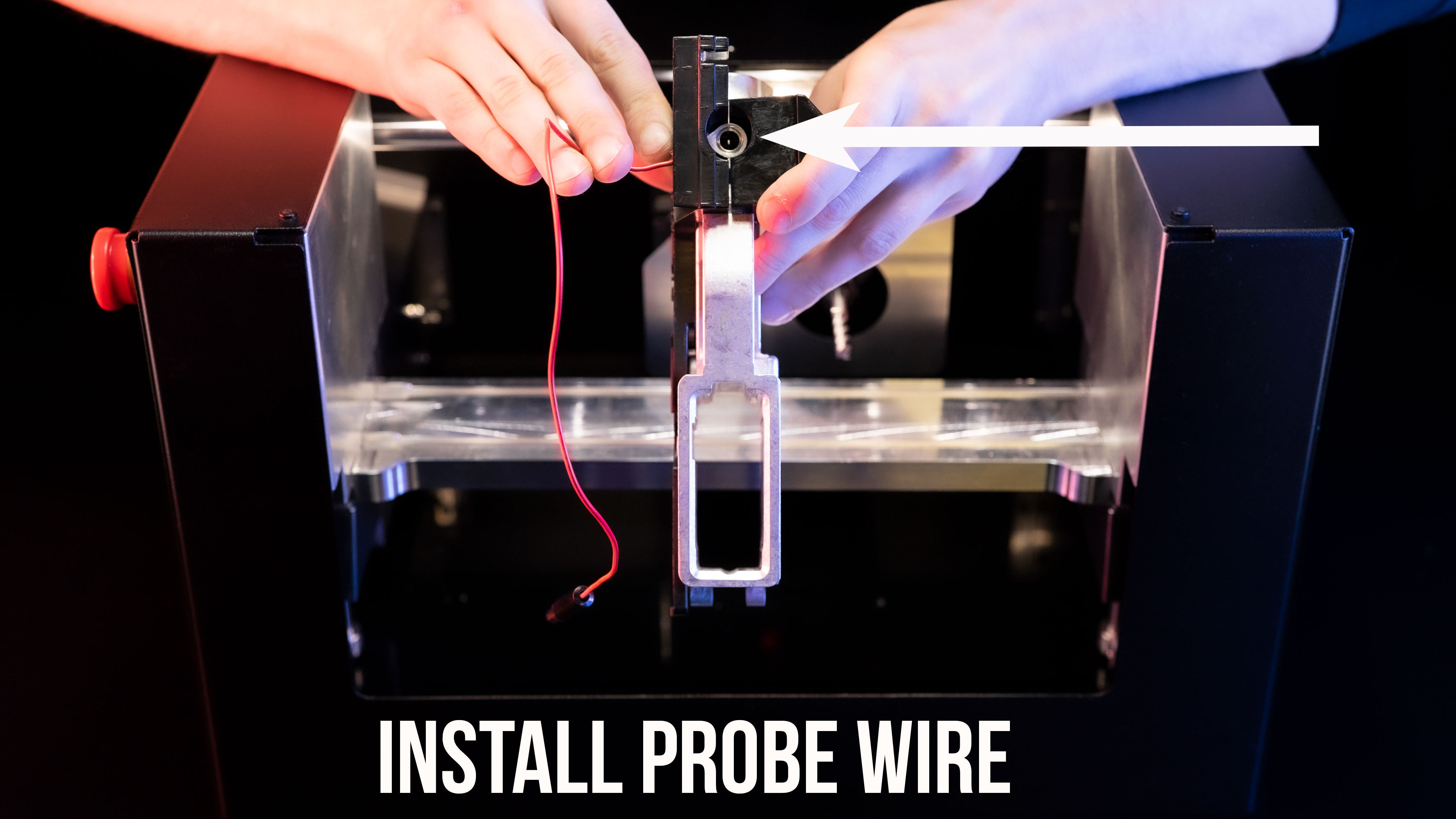
Replacing or Reseating Probe Wire
Ghost Gunner 3 | Spare probe wires are available on our website with the following link.
Ghost Gunner 2 | Use the following instructions to replace your GG2 probe wire:
1. Use a 2.5mm allen to remove 7 bolts securing the Ghost Gunner’s rear panel.
2. Turn the machine upside-down. Take care not to lean it on its stepper motors.
Note | Aluminum chip can cause electronics to short. Thoroughly vacuum all aluminum chip. Use a paintbrush to free up any chip stuck to components. The inside of the machine must be completely free of aluminum chip prior to opening the electronics enclosure.
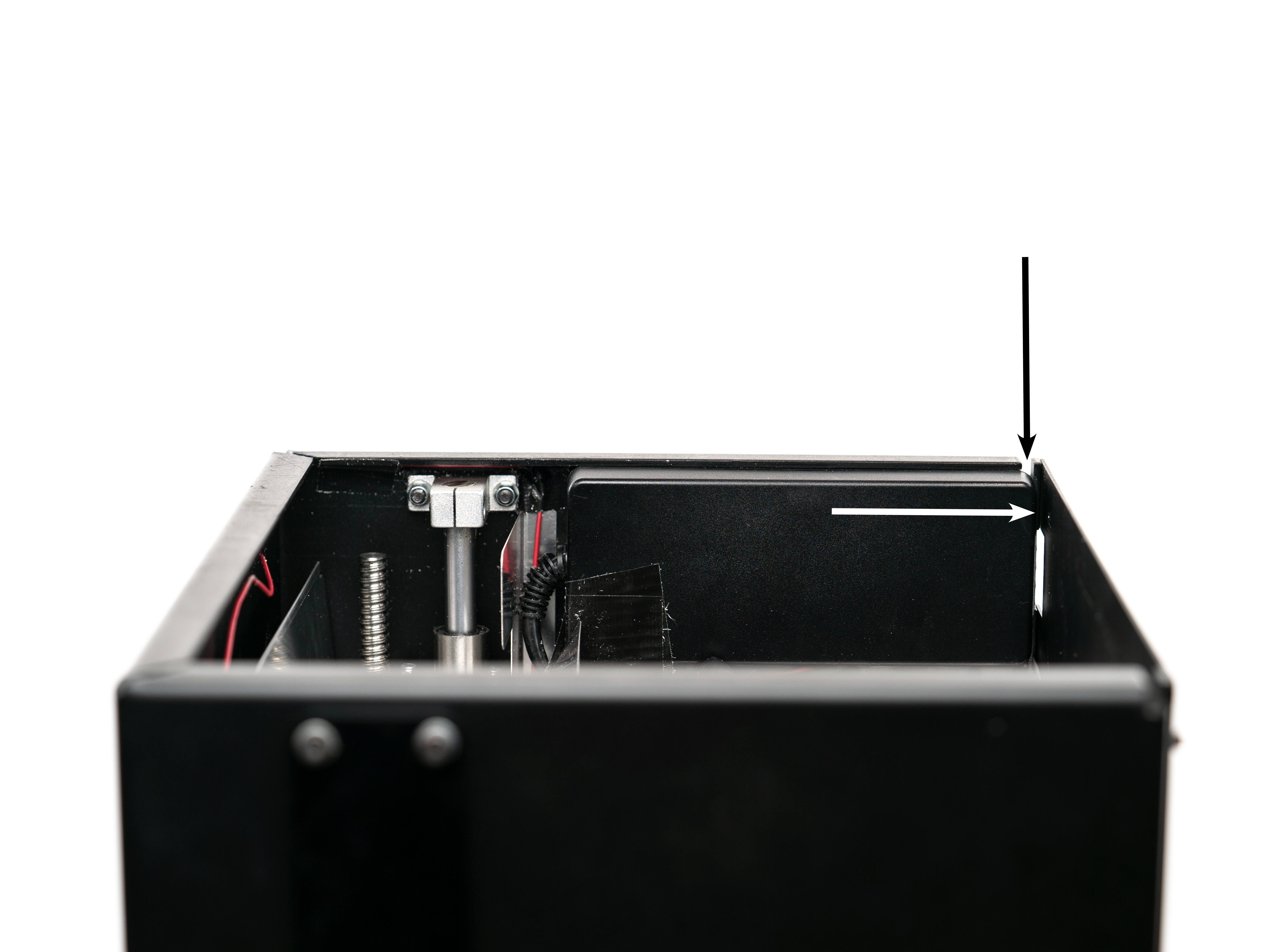
3. The power supply is held tight to the inner wall of the machine with an adhesive. Pry the power supply off of the wall using a large flathead screwdriver inserted from the slot in the corner as shown in following image (A1). It requires a great deal of force to break the power supply away from the VHB tape so don’t hesitate to put to some muscle into it.
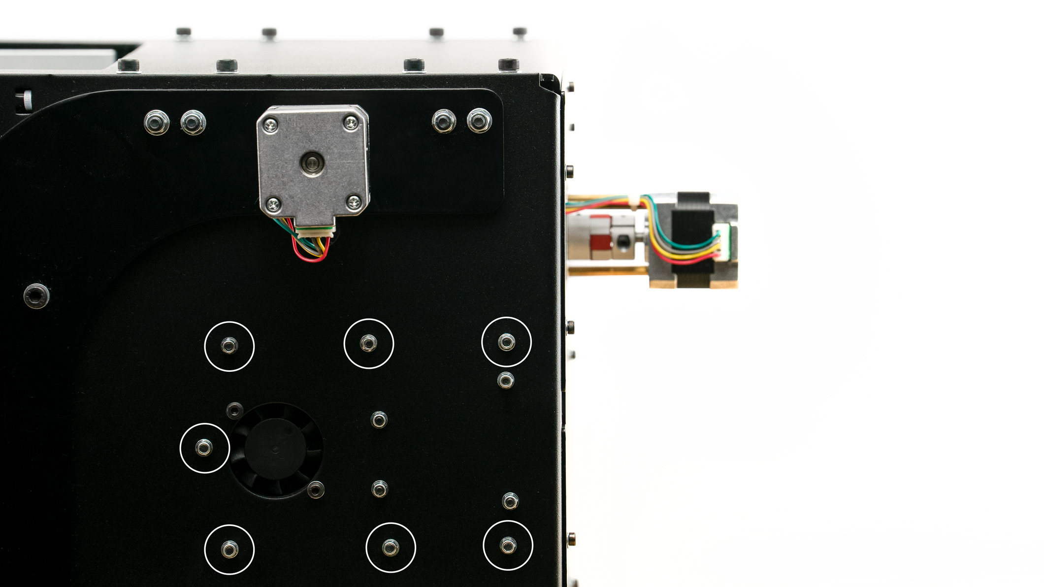
4. Use a 2.5mm allen and 5.5 mm socket to remove 7 bolts that secure the electronics enclosure to the wall as shown in below image (A2, marked white). Take care to not damage wires.
Note | The control board is stacked onto an Arduino board.
Caution | Do not separate the control board from the Arduino.
Caution | Do not disconnect other wires from the control board.
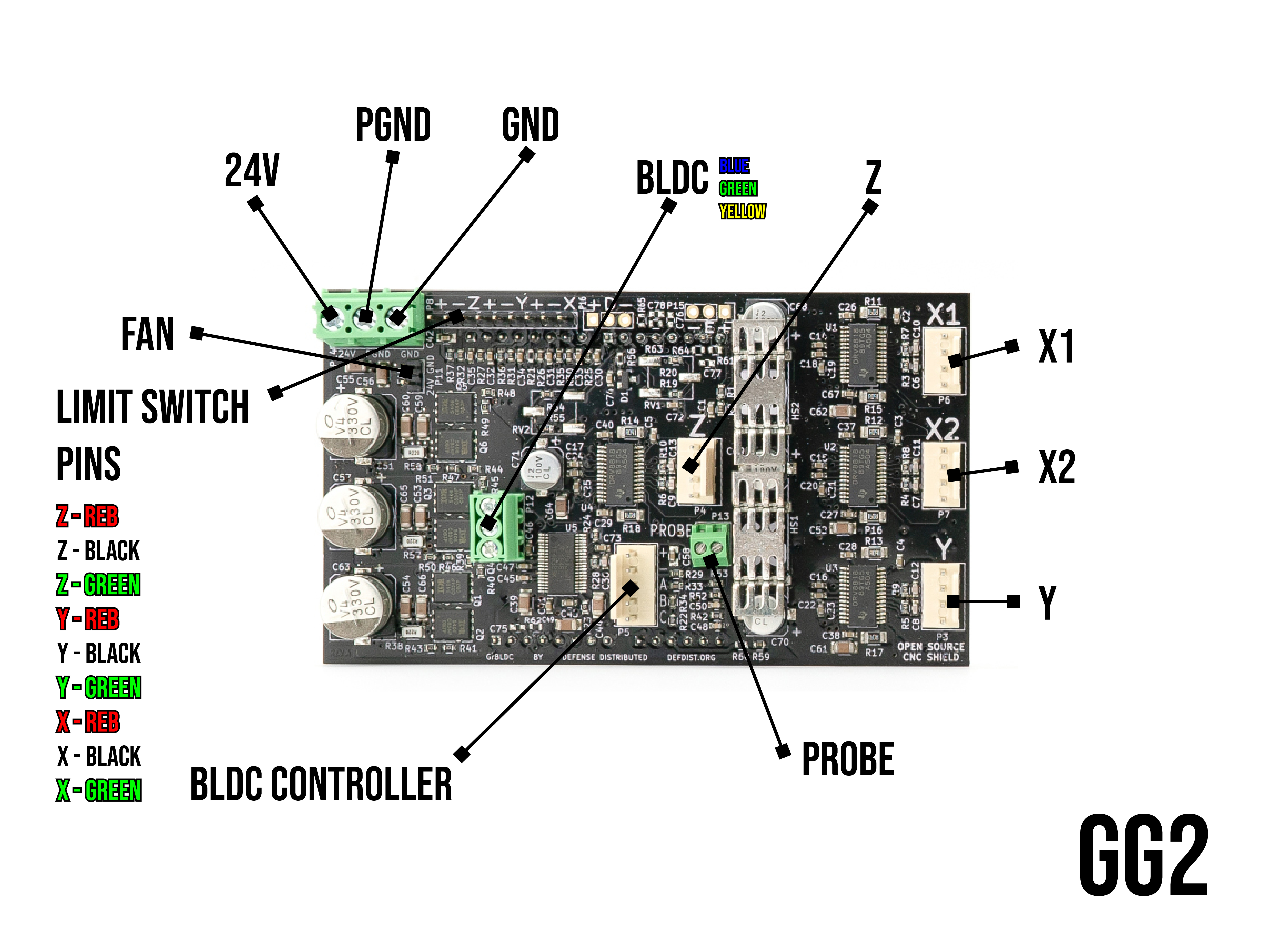
5. Locate the probe connection on the control board.
6. An eyeglass repair screwdriver can be used to loosen the set screw, reseat the probe wire, then tighten the set screw.
7. Once the wire is inspected and reseated, connect the USB cable between the GG and computer.
8. Hold the probe wire eyelet away from the machine and use a voltmeter set to 20V DC to measure the voltage between the eyelet of the red wire and the spindle. You should read 5V DC +/-0.5V between the spindle and probe wire eyelet.
9. If you don’t read any voltage, replace the probe wire.
10. Reinstall electronics enclosure and secure 7 bolts.
Caution | Take care not to twist or pinch wires. All wiring should route through the small opening in the electronics enclosure.
11. Reattach power supply to wall. A piece of VHB tape will be necessary.
12. Reattach the Ghost Gunner’s rear panel and secure 7 bolts.
Comments
0 comments
Please sign in to leave a comment.